
Pump Sizing Calculator

TDH
= Static Head + Friction Head + Pressure Head
Vertical distance between fluid source and discharge point
ft
Total friction losses through pipe, fittings, and valves
ft
Leave at 0 if suction and discharge pressures are equal
ft
Total Dynamic Head
0
ft
Meters
0
m
PSI
0
psi
Bar
0
bar
NPSHa
= Atm Head +/- Suction Head - Friction - Vapor Pressure
Standard = 33.9 ft at sea level
ft
Positive above centerline, negative below
ft
Friction in suction piping only
ft
Water at 68°F = 0.78 ft
ft
From manufacturer data sheet
ft
NPSHa
0
ft
NPSHr
0
ft
NPSH Margin
0
ft
Cavitation Risk
BHP
= (Flow x TDH x SG) / (3960 x Efficiency)
GPM
ft
Typical centrifugal pump: 70 to 85%
%
Water = 1.0
SG
Required BHP
0
hp
Required kW
0
kW
Recommended Motor
0
hp
Service Factor
1.15
SF
GPM
0
L/min
0
m³/h
0
L/s
0
CFM
0
Pump Curve
Enter TDH values and hit Calculate to see the curve
Need expert sizing support for your application?
Contact Rhino Pumps

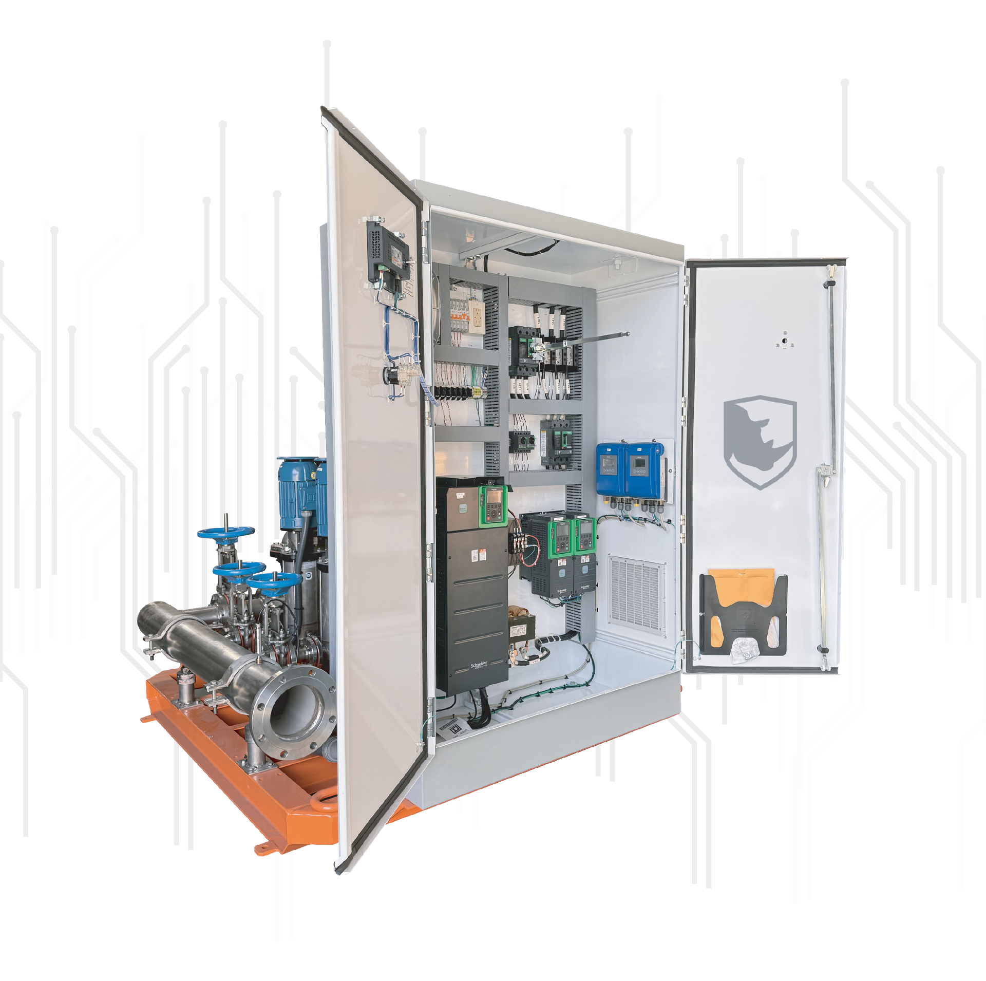
VFD integration for pump systems built in a UL 508A listed panel shop. How proper integration delivers energy savings, reliability, and code compliance.

Can Rhino Pumps match your controls, meet your bid spec, handle your slurry or biosolids? Straight answers on engineering, custom systems, and service.
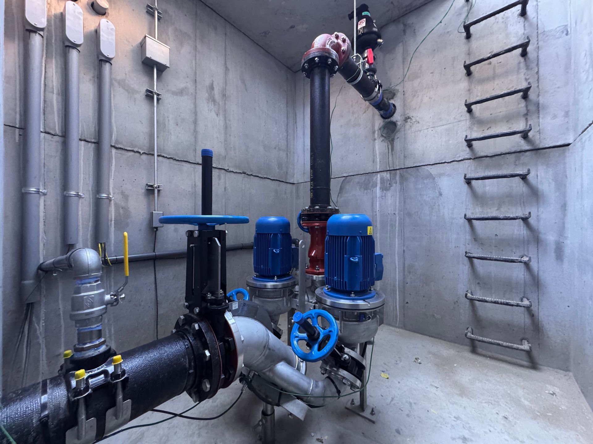
How integrated wastewater pump and monitoring systems improve treatment reliability through real time visibility, early warning, and faster response.
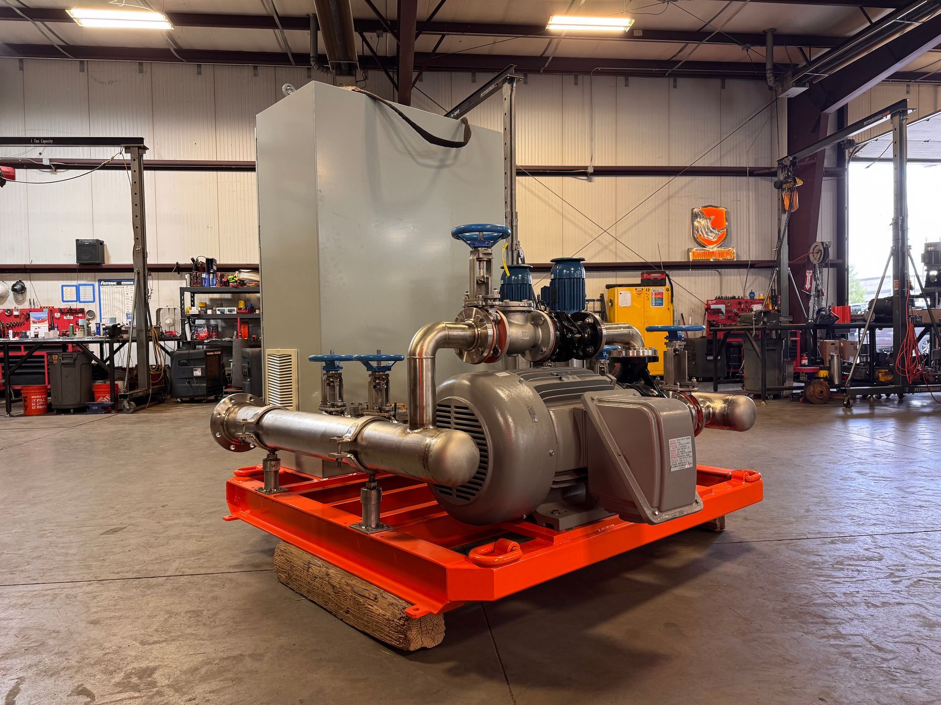
An integrated pump package delivers the pump, controls, and instrumentation as one factory-tested unit. How integration improves reliability and uptime.

How vertical turbine pump systems improve deep mine dewatering reliability, why custom engineering matters, and how Rhino Pumps builds them to the mine.
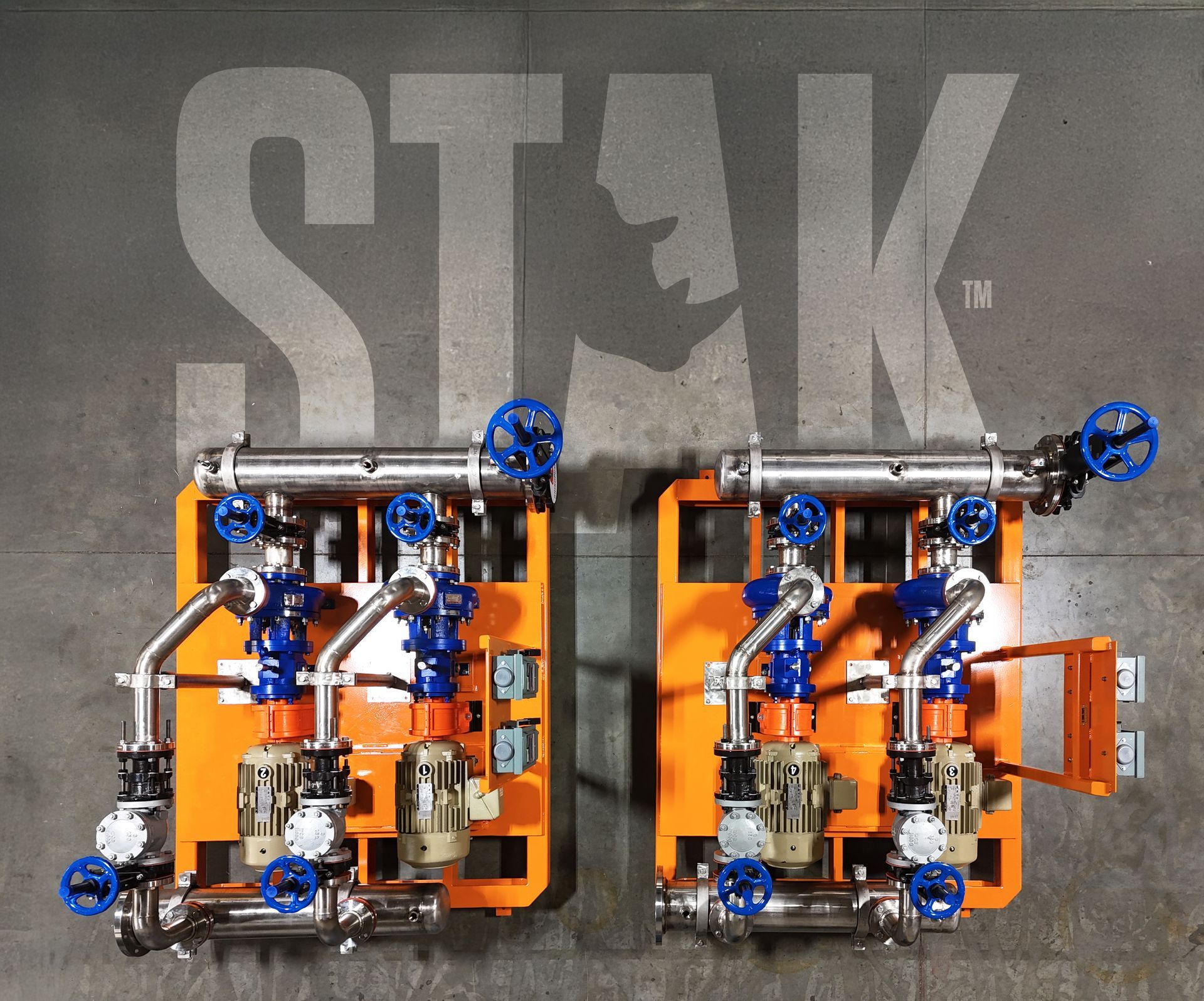
Why custom engineered pump solutions matter for complex industrial processes, when to choose custom over catalog, and how RhinoStak is built to your process.